Guide to GIGA R1 Dual Cores
Learn how to access and control the M4 and M7 cores on the GIGA R1, and how to communicate between them using RPC.
The GIGA R1's STM32H747XI has two cores, the M4 and the M7. Each core can be programmed individually, with M7 acting as the main processor, and the M4 as a co-processor.
The M7 is referred to as the main processor due its superior hardware features, as well as it is required to run to boot the M4 core (you boot the M4 from within the M7).
These two cores can run applications in parallel, for example, running a servo motor on one core, and a display on another, without blocking each other. In a single core, such operations would slow down the program, resulting in lesser performance.
The M4 and M7 cores are programmed with separate sketches, using the same serial port. In the Arduino IDE, you can select the core you want to program, and then upload the sketch you want to run on that specific core.
Goals
In this guide you will discover:
- How to configure and program the M4/M7 cores and conventional approaches to do so.
- How to boot the M4 core.
- How to communicate between the cores via Remote Call Procedures (RPC).
- Useful examples based on the dual core & RPC features.
- The
library API.RPC
Hardware & Software Needed
- GIGA R1 WiFi
- Arduino IDE
- Arduino GIGA Board Package installed.*
*For instructions on how to install the GIGA Board Package, follow the Getting Started with GIGA R1 guide.
M4 Support
The M4 processor can access most of the peripherals that the M7 can access, with some exceptions.
The M4 supports:
- I2C
- SPI
- UART
- CAN
- DAC
- ADC
- Bluetooth® Low Energy (via ArduinoBLE Library)
The M4 does not support:
- Wi-Fi®
- Serial communication*
- Arduino Cloud sketches.
*Serial Communication from the M4 can be enabled by setting up an RPC that allows the M4 & M7 cores to communicate. Using
(M4) and RPC.print()
(M7) helps achieve this. See RPC Serial Example.RPC.read()
Boot / Disable M4
The M4 core is by manufacturing default, disabled when booting the board. The M4 core can however be booted by using the
RPC.begin()Boot / Disable M7
The M7 is booted by default and there is currently no option to disable this core.
Peripheral Interference
When booting the M4, the M4 will execute the sketch that has been uploaded to its flash memory. It is a good idea to track what type of code you are running on the M4, as you may create interference between different peripherals. If you run simply a blank sketch on the M4, it should not create any interference.
An example of this is if you use the
CANTip: name your sketches with a
and _M4
suffix/prefix, and create an initialization sequence. E.g. blink the blue LED three times whenever the M4 boots up._M7
Pin Priority
As the M7 and M4 core share their pins, which one gets priority to the pin? It can be assumed that as the M7 is the more powerful core, it gets first access.
This is however not true as pin priority is random. If both cores tries to access the same pin (e.g.
D27When developing dual core applications, it is a good idea avoiding using the same pins & peripheral for many reasons.
Programming M4/M7
When programming the GIGA R1 WiFi's M7 and M4, we create a sketch for each core, and program them like we would program two individual Arduino boards. As only a single serial port is available, we need to specify which core we want to target.
Some essential things to consider when programming the cores are:
- You need to partition the memory, allocating flash memory to the M4 core.
- You need to select the target core, which is either Main Core or M4 Co-processor.
- The M4 has no serial communication enabled, here we need to use RPC (see RPC Serial example).
When writing multiple sketches, there are some things to consider to make your development experience easier:
- Name your sketches with either
or_M4
suffix or prefix. This will make it easier if the code is intended to be shared with others._M7 - Consider having a starting sequence (e.g. the blue LED blinking 3 times), whenever a core is initialized.
- Always include
on your M7 core sketch.RPC.begin()
Partitioning The Flash Memory
To allocate the flash memory for the M4, the flash memory can be partitioned. This is done by navigating to Tools > Flash Split in the IDE.
Note that the flash memory is the space where the application code (your sketch) is stored. It is not the RAM memory (which is significantly lower).
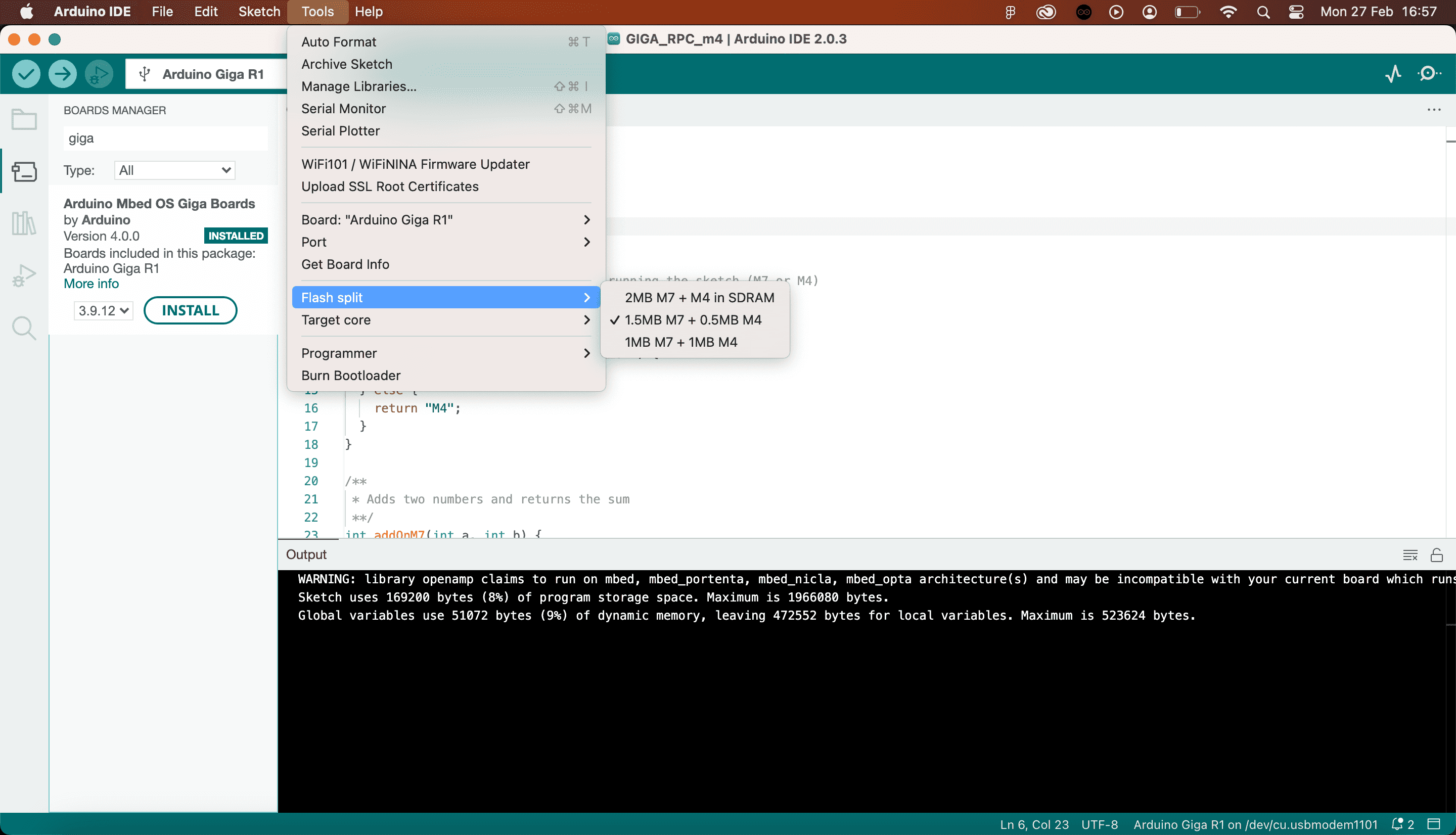
- 2MB M7 + M4 in SDRAM (default) - this option is the default configuration, which is for programming the M7 only. This allocates no flash memory to the M4.
- 1.5MB M7 + 0.5MB M4 - useful when larger amount of flash memory is required on the M7.
- 1MB M7 + 1MB M4 - useful when you need to balance the flash memory equally between the M4 and M7 cores.
It is required to use option 2 or 3 if you intend to program the M4 via the IDE, as the default option provides no memory allocation for the M4.
Target Core
To select the core you want to program, navigate to Tools > Target Core in the IDE.
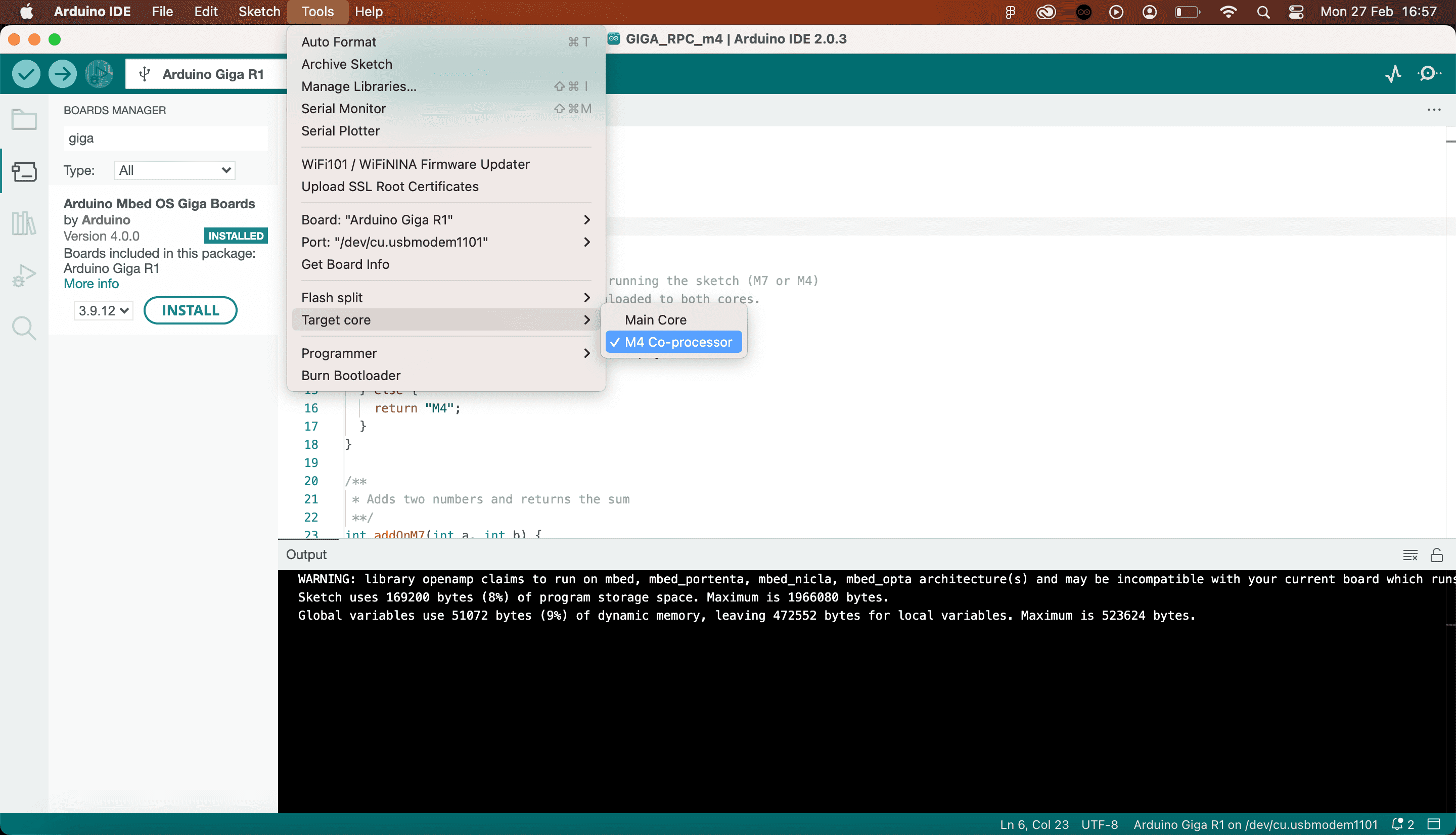
Here you can choose between:
- Main Core - this is the M7 core, the main processor on the board.
- M4 Co-processor - this is the M4 core, the co-processor on the board.
Uploading
As both cores share the same serial port, choosing the Flash Split + Target Core is required so that the program is uploaded to the correct core.
Uploading is no different than to any other Arduino board: simply click the upload button and wait for it to finish.
Booting M4 Core
The M4 core does not boot by itself as it requires interaction from the M7 core. This boot function is built into the
RPC1#include <RPC.h>2
3void setup() {4 RPC.begin(); //boots M45}6void loop(){7}Once the M4 is booted from the M7, both cores will run in parallel, much like two Arduinos sharing the same board.
Writing Over Existing Sketch
Uploading new sketches works the same as a typical upload procedure. The new sketch will overwrite the current sketch running on the core you upload to.
Identify Core Used
To identify which core is being used, use the
HAL_GetCurrentCPUID()1/*2GIGA R1 WiFi - Core identify sketch.3
4This simple sketch blinks an LED on boot.5You will need to upload it to both the M7 and M4 core.6
7It checks whether current CPU is M7 or M4, and blinks either 8the blue LED or the green LED, 10 times. 9
10As the M4 is booted when invoking RPC.begin() on the M7,11the M4 sketch will run as soon as the blink() function12finishes on the M7. 13*/14
15#include <RPC.h>16
17void setup() {18 pinMode(LEDB, OUTPUT);19 pinMode(LEDG, OUTPUT);20
21 if (HAL_GetCurrentCPUID() == CM7_CPUID) {22 blink(LEDB, 100); //blink blue LED (M7 core)23 } else {24 blink(LEDG, 100); //blink green LED (M4 core)25 }26}27
28void loop() {29}30
31void blink(int led, int delaySeconds) {32 for (int i; i < 10; i++) {33 digitalWrite(led, LOW);34 delay(delaySeconds);35 digitalWrite(led, HIGH);36 delay(delaySeconds);37 }38 RPC.begin();39}- The
is a method that checks the CPU ID, and returns the value in aHAL_GetCurrentCPUID()
format.uint32_t - The
flag that we compare with holds the valueCM7_CPUID
(hexadecimal), or0x00000003
(decimal).3 - It is also possible to use
flag which holds the valueCM4_CPUID
, or0x00000003
(decimal).1
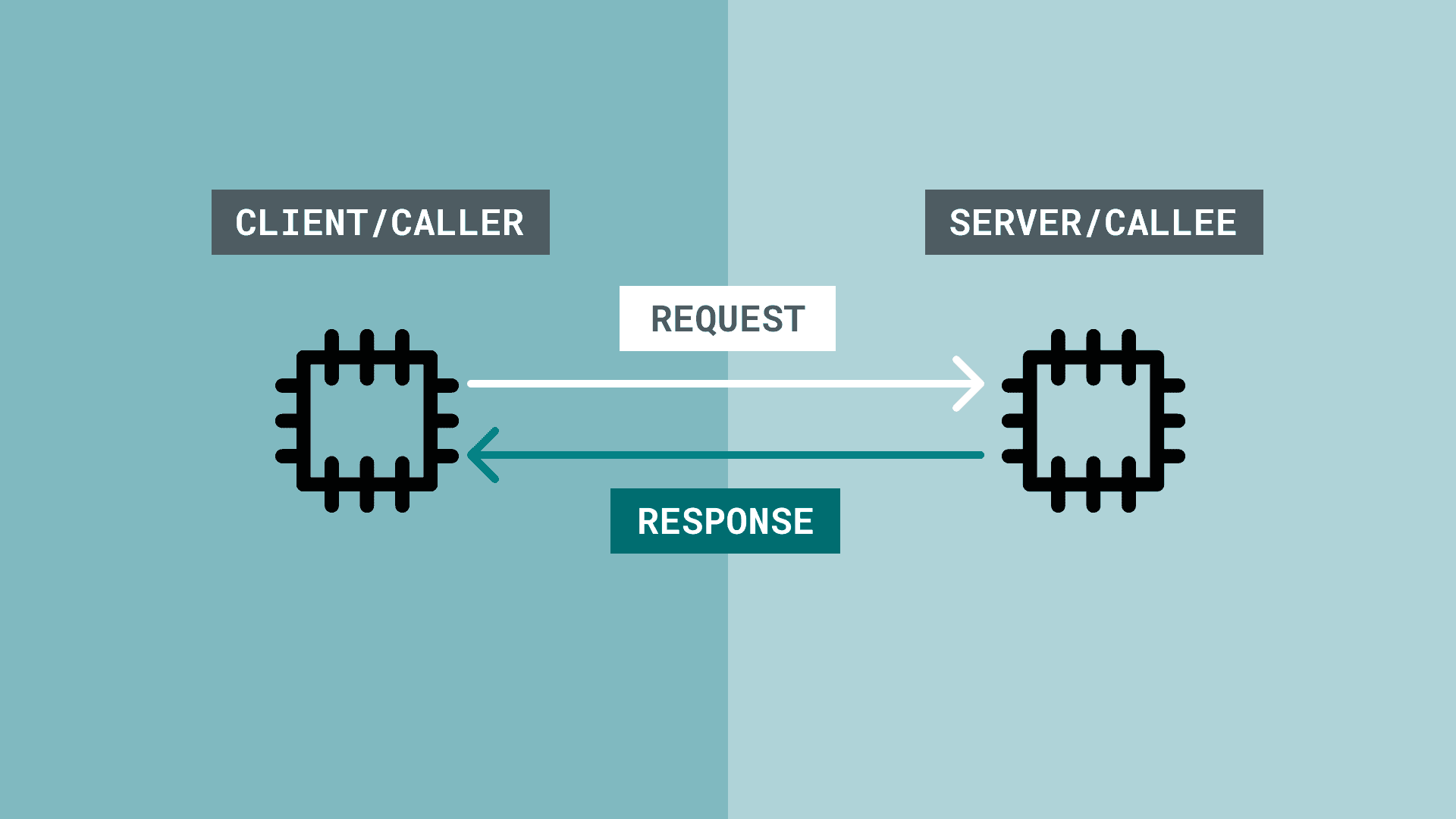
Remote Call Procedures (RPC)
RPC is a method that allows programs to make requests to programs located elsewhere. It is based on the client-server model (also referred to as caller/callee), where the client makes a request to the server.
An RPC is a synchronous operation, and while a request is being made from the caller to another system, the operation is suspended. On return of the results, the operation is resumed.
The server side then performs the subroutine on request, and suspends any other operation as well. After it sends the result to the client, it resumes its operation, while waiting for another request.
RPCs in the Arduino Environment
At the moment, only a limited amount of boards supports RPC, as in this context, it is designed to be a communication line between two cores. The GIGA R1 is one of them.
What makes this implementation possible is the
RPCThe library makes it possible to set up either of the M4/M7 cores as a server/client, where remote calls can be made between them. This is done by "binding" a function to a name on the server side, and calling that function from the client side.
On the server side, it could look like this:
1//server side, for example M72int addFunction(int a, int b){ 3 return a + b;4}5
6RPC.bind("addFunction", addFunction);On the client side, it could look like this:
1int x,y = 10;2
3RPC.call("addFunction", x, y);When
call()xy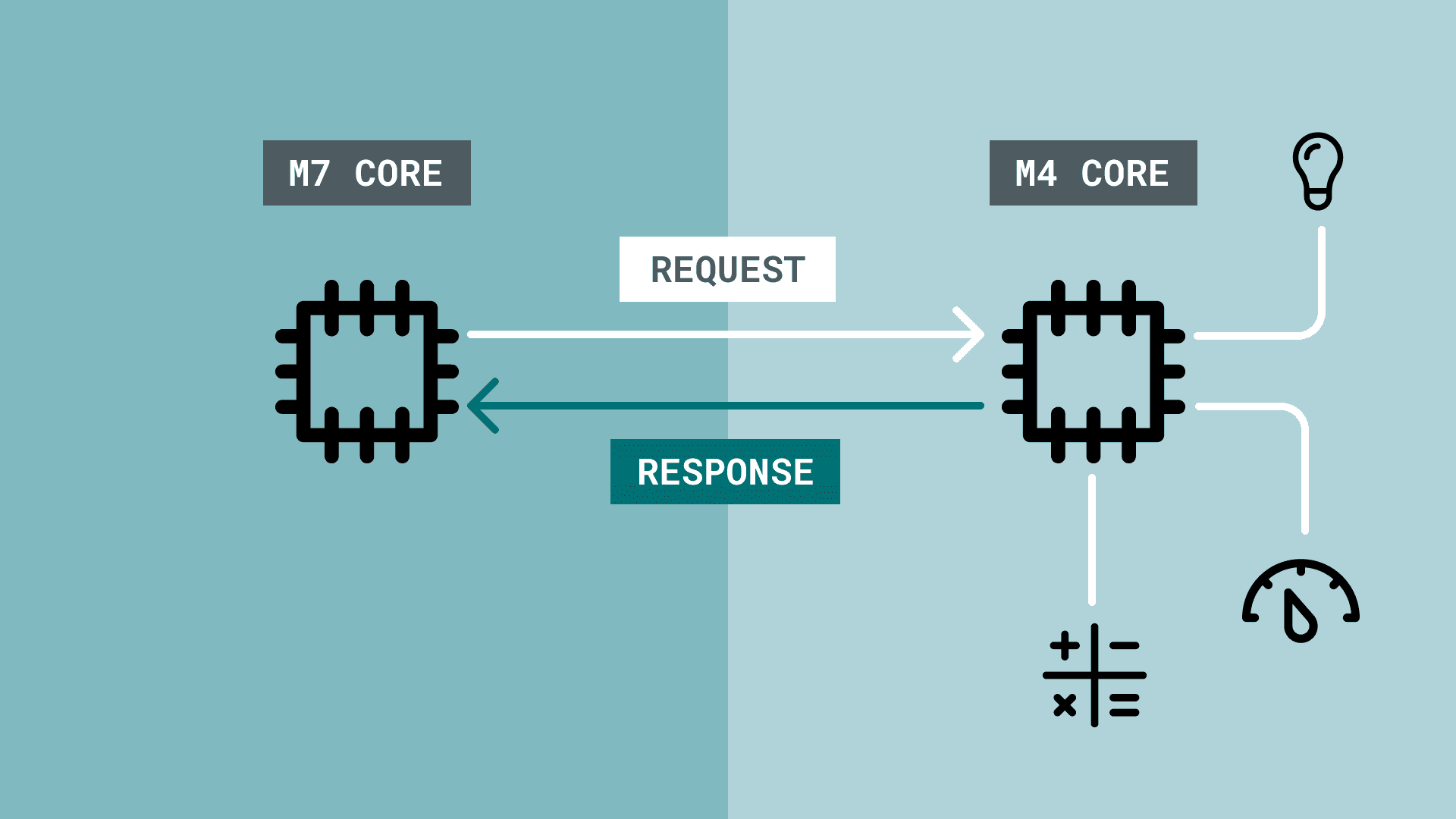
RPC Examples
In this section, you will find a series of examples that is based on the
RPCRPC Serial
The
Serial.print()- Use
on the M4. This will print the values to the RPC1 stream.RPC.println() - Use
andRPC.available()
.RPC.read()
M4 Sketch:
1#include <RPC.h>2
3void setup() {4RPC.begin();5}6
7void loop() {8RPC.println("Printed from M4 core");9delay(1000);10}M7 Sketch:
1#include <RPC.h>2
3void setup() {4Serial.begin(9600);5RPC.begin();6}7
8void loop() {9 String buffer = "";10 while (RPC.available()) {11 buffer += (char)RPC.read(); // Fill the buffer with characters12 }13 if (buffer.length() > 0) {14 Serial.print(buffer);15 }16}RPC Sensor
This example demonstrates how to request a sensor reading from one core to the other, using:
- M4 as a client.
- M7 as a server.
M4 Sketch:
1#include "Arduino.h"2#include "RPC.h"3
4using namespace rtos;5
6Thread sensorThread;7
8void setup() {9 RPC.begin();10 Serial.begin(115200);11
12 /*13 Starts a new thread that loops the requestReading() function14 */15 sensorThread.start(requestReading);16}17
18void loop() {19}20
21/*22This thread calls the sensorThread() function remotely23every second. Result is printed to the RPC1 stream.24*/25void requestReading() {26 while (true) {27 delay(1000);28 auto result = RPC.call("sensorRead").as<int>();29 RPC.println("Result is " + String(result));30 }31}M7 Sketch:
1#include "Arduino.h"2#include "RPC.h"3
4void setup() {5 RPC.begin();6 Serial.begin(115200);7
8 //Bind the sensorRead() function on the M79 RPC.bind("sensorRead", sensorRead);10}11
12void loop() {13 // On M7, let's print everything that is received over the RPC1 stream interface14 // Buffer it, otherwise all characters will be interleaved by other prints15 String buffer = "";16 while (RPC.available()) {17 buffer += (char)RPC.read(); // Fill the buffer with characters18 }19 if (buffer.length() > 0) {20 Serial.print(buffer);21 }22}23
24/*25Function on the M7 that returns an analog reading (A0)26*/27int sensorRead() {28 int result = analogRead(A0);29 return result;30}RPC Servo Motor
This example demonstrates how to request a servo motor on another core to move to a specific angle, using:
- M4 as a client.
- M7 as a server.
Each example is written as a single sketch intended to be uploaded to both cores.
M4 sketch:
1#include "Arduino.h"2#include "RPC.h"3
4using namespace rtos;5
6Thread servoThread;7
8void setup() {9 RPC.begin();10 Serial.begin(115200);11
12 /*13 Starts a new thread that loops the requestServoMove() function14 */15 servoThread.start(requestServoMove);16}17
18void loop() {19}20
21/*22This thread calls the servoMove() function remotely23every second, passing the angle variable (0-180).24*/25void requestServoMove() {26 while (true) {27 //Read a pot meter28 int rawAnalog = analogRead(A0);29
30 //Map value to 18031 int angle = map(rawAnalog, 0, 1023, 0, 180);32
33 delay(1000);34 auto result = RPC.call("servoMove", angle).as<int>();35 RPC.println("Servo angle is: " + String(result));36 }37}M7 sketch:
1#include "Arduino.h"2#include "RPC.h"3#include <Servo.h>4
5Servo myservo;6
7void setup() {8 RPC.begin();9 myservo.attach(5); //attach servo to pin 510
11 Serial.begin(115200);12
13 //Bind the servoMove() function on the M714 RPC.bind("servoMove", servoMove);15}16
17void loop() {18 // On M7, let's print everything that is received over the RPC1 stream interface19 // Buffer it, otherwise all characters will be interleaved by other prints20 String buffer = "";21 while (RPC.available()) {22 buffer += (char)RPC.read(); // Fill the buffer with characters23 }24 if (buffer.length() > 0) {25 Serial.print(buffer);26 }27}28
29/*30Function on the M7 that returns an analog reading (A0)31*/32int servoMove(int angle) {33 myservo.write(angle);34 delay(10);35 return angle;36 /*37 After the operation is done, return angle to the client.38 The value passed to this function does not change, but this39 verifies it has been passed correctly.40 */41}RPC Library API
The
RPCThis library is included in the GIGA Board Package, so it is automatically installed with the Board Package. To use this library, you need to include
RPC.h1#include <RPC.h>RPC.begin()
Initializes the library. This function also boots the M4 core.
Syntax
1RPC.begin()Returns
on success.1
on failure.0
RPC.bind()
Used on the server side to bind a name to a function, and makes it possible for remotely calling it from another system.
Syntax
1RPC.bind("this_function", thisfunction)Parameters
- name given for the function to be called from the client side."name_of_func"
- name of the function on the server side.name_of_func
Returns
- None.
RPC.call()
Used on the client side to call a function with optional parameters.
1RPC.call("this_function", int args)Parameters
- the name of the function declared on the server side."name_of_func"
- arguments to be passed to the function.args
Returns
- Result of the function if arguments are passed.
RPC Serial API
The RPC Serial methods are also included in the
RPCAs the
SerialRPCRPC.println()
Prints data to a serial port. This is used on the M4 core to send data to the M7.
Syntax
1RPC.println(val);Parameters
- The value to print. Can be any data type, but not multiple (e.g. string + integer in the same call).
Returns
- Number of bytes used. E.g. printing ("hello") returns 7. As hello (5) + new line (2) = 7.
RPC.available()
Get the number of available bytes to read from the M4.
Syntax
1RPC.available();Parameters
- None.
Returns
- The number of bytes available to read.
if there is none.-1
RPC.read()
Reads the first available byte from the M4.
Syntax
1RPC.read();Parameters
- None.
Returns
- The first available byte from the M4.
if there is none.-1
Suggested changes
The content on docs.arduino.cc is facilitated through a public GitHub repository. You can read more on how to contribute in the contribution policy.
License
The Arduino documentation is licensed under the Creative Commons Attribution-Share Alike 4.0 license.